No More Prototyping
The last few weeks leading to Pi Wars were extremely busy. After a long time spent prototying and experimenting freely, our team now realised there wasn’t much time left and we were rushing to finish building a “final” version of the robot, suitable for the competition.
We didn’t have any time to update the blog, so this post is slightly late… We’re still catching up, so more posts will follow about the competition!
In theory, the plan was clear and straightforward: we learned a lot from the prototypes and knew what worked, what needed changing, which features were essential, and which ones could be left out or simplified. But this “final build” essentially meant a complete rebuild of the robot and every detail of this had to come together just right, with very little or no time to test.
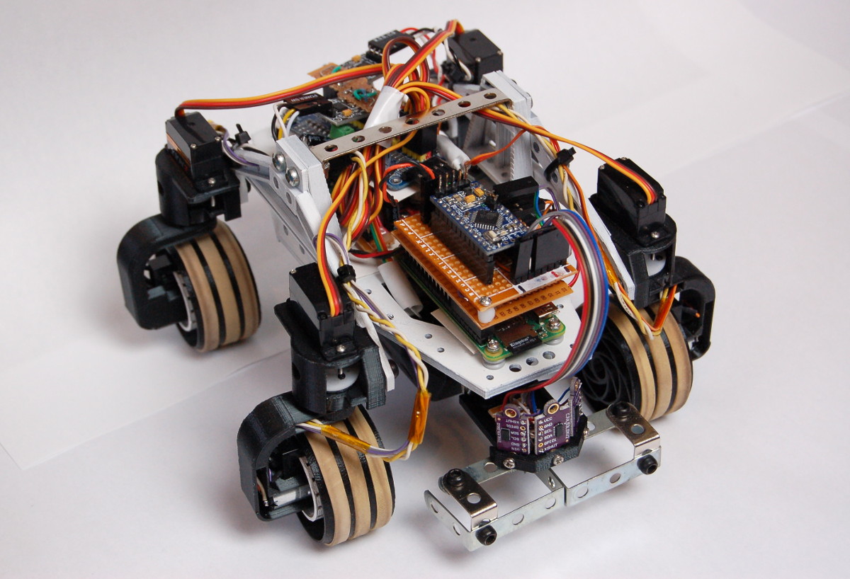
So here is a list of all the final components:
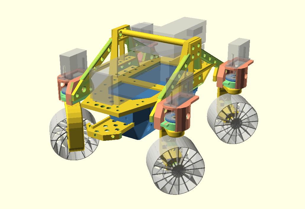
MOSS – MObility SyStem
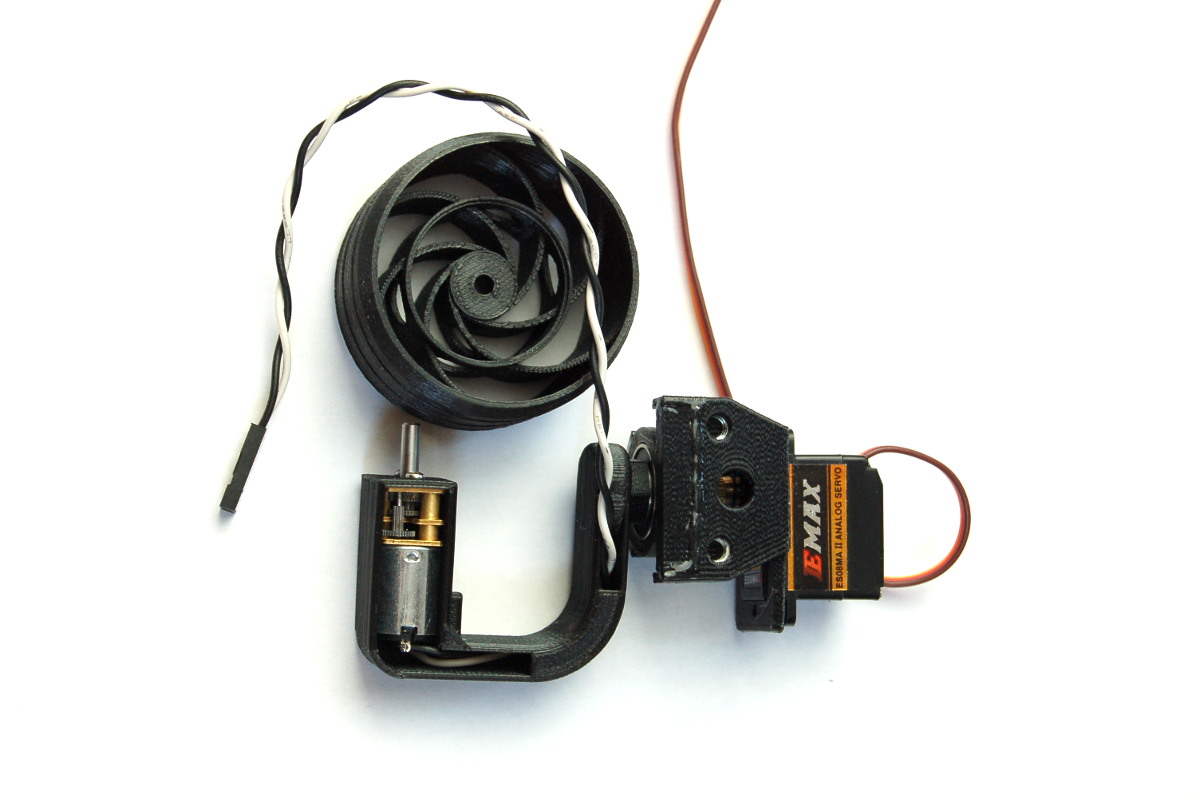
The MOSS has four identical units: two at the front, and two at the back, all attached at equal distances from the center of the rover’s body. Each unit comprises a drive motor (N20 gear motor, 200 RPM), a steering servo (ES08MA, metal gears) and a wheel.
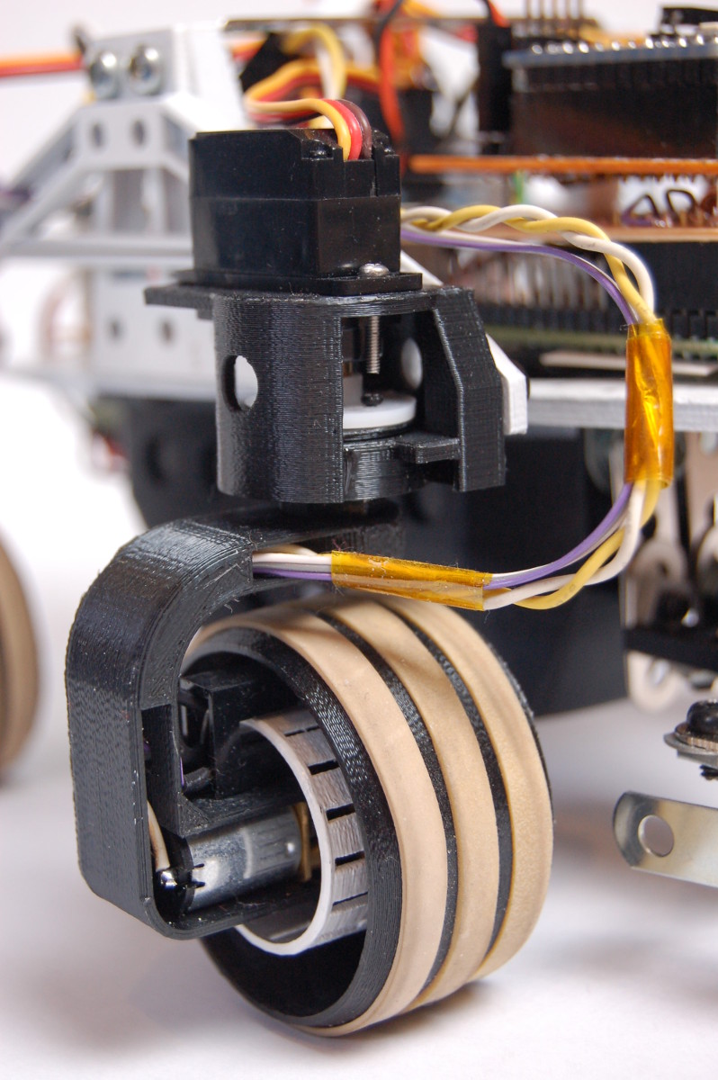
The servo rotates the whole motor holder with the center of rotation going right through the middle of the wheel. Inside the servo holder there is a small ball bearing which provides a very solid rotating platform: the motor holder and the servo shaft are both connected to its inner ring, so the servo doesn’t need to directly support any weight. The motor holder also provides a conduit for the cables.
(This design is an improved version of the one used for the MRV0.3: the wheels and the wheel holders are slightly smaller and lighter. The servo holder is much smaller and the servo - ball bearing connection is much more solid. The servos are the same, but the motors are twice as fast.)
The fully assembled version also has an encoder wheel (a cylinder with holes) and an optical sensor attached to the motor holder. The plan was to use these for speed measurement, but the rest of the required parts were not completed in time.
CBSU – Central Body Support Unit
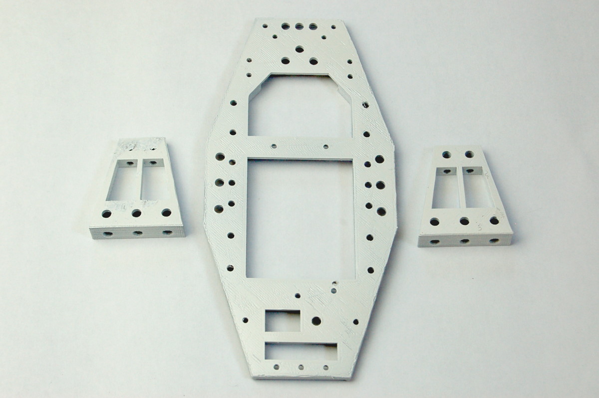
The CBSU is the frame that holds all the other parts of the body together: it has a flat, octagonal “deck” with two “towers” on each side, where the “legs” (not shown on the picture) with the MOSS units are attached. The PM-1 (battery holder) is attached below the deck. Sensors or special attachments are connected to the front and all the other electronics units sit on the top.
PM-1 – Power Module 1
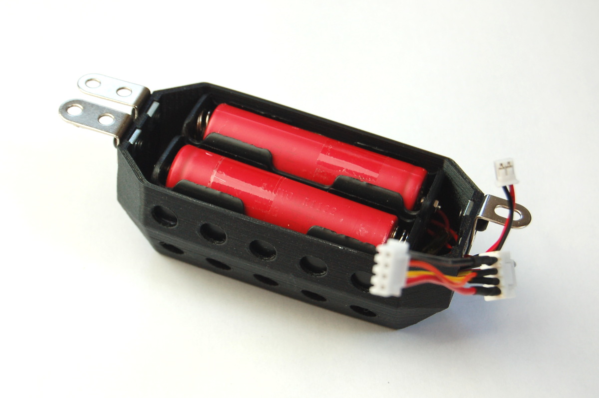
The PM-1 contains 2 (in series) + 1 18650 LiIon cells and protection circuits, providing two separate voltages (nominal 3.7V for the electronics and 7.4V for the motors). This separation ensures the electronics is isolated from any noise from the motors.
PM-1 also provides direct connections to the individual battery terminals: these can be used for battery charge monitoring (not implemented yet).
P-CAMS – Power Conversion And Management System
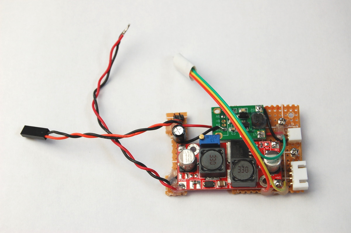
The P-CAMS sits on the deck, directly above the PM-1. It has two DC-DC converters: one fixed 5V boost converter for the electronics and a variable buck-boost converter to provide about 6V for the motors and servos. (The rover is turned on by connecting the two connectors of PM-1 to the P-CAMS.)
The P-CAMS also has outputs that could be connected directly to the SIPS for battery charge monitoring (it also has a voltage divider to scale down the voltage from the 2S cells), but this wasn’t used at the end.
ACF-MAS – Actuator Controller For Motors And Servos
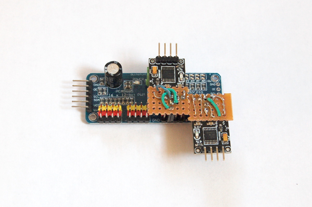
The ACF-MAS is responsible for driving the motors and the servos: it comprises a PCA9685 board with 16 PWM outputs and two DRV8833 2-channel motor drivers with motor connectors facing left and right. The servos are connected directly to the PCA9685 board connectors. The MECCAPU controls the ACF-MAS using I2C.
MECCAPU – Mars Exploration Central Computing And Processing Unit
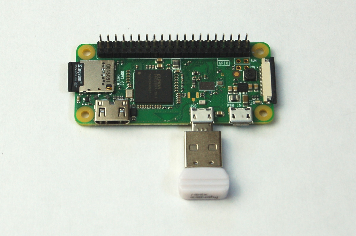
The MECCAPU (a Raspberry Pi Zero W) is responsible for the overall control of the rover. Apart from the built-in WiFi (set up as an access point), it also includes a receiver for direct remote control from Earth (a dongle for a Rock Candy PS3 controller). The main control program running on the MECCAPU also provides telemetry (sensor data, current speed and orientation, additional debugging from autonomous controller programs) that can be processed by a visualiser program running in the control center on Earth (or a laptop that connects to the rover’s WiFi).
CREMCOAM – Central RElay Module for Connection Of All Modules

The CREMCOAM sits between the MECCAPU and the SIPS. It looks very simple but its role is vital: it connects all the electronics modules together. It connects the serial pins of the MECCAPU to the SIPS via a 5V – 3.3V level shifter and also provides a connector to the ACF-MAS (I2C). It receives the 5V supply from the SIPS and provides a power connector to the MECCAPU.
SIPS – Sensor Information Processing Subsystem
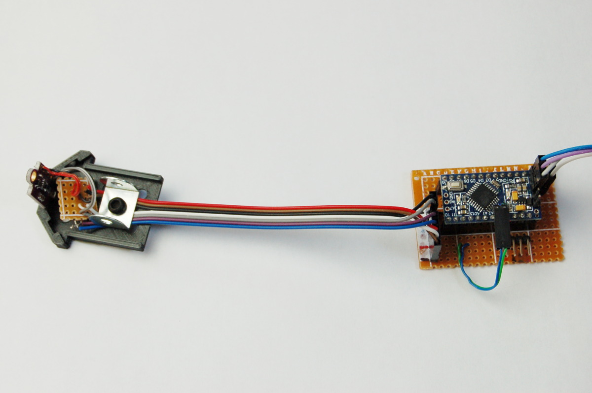
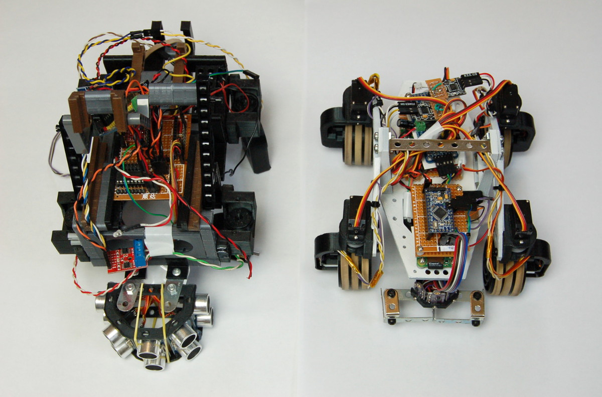
The SIPS (shown in the right of the picture, with the half-assembled FAROS attached) is responsible for low-level real-time tasks. It’s Arduino Pro Mini clone running at 5V. Currently it only handles distance sensor measurement data, but the orignal plan also included speed measurement from the optical sensors on the wheels and battery charge monitoring. It can also show some very simple status information with an integrated LED using three different blinking modes. The SIPS is connected via CREMCOAM to the MECCAPU using the serial interface.
FAROS – Frontal ARray Of Sensors
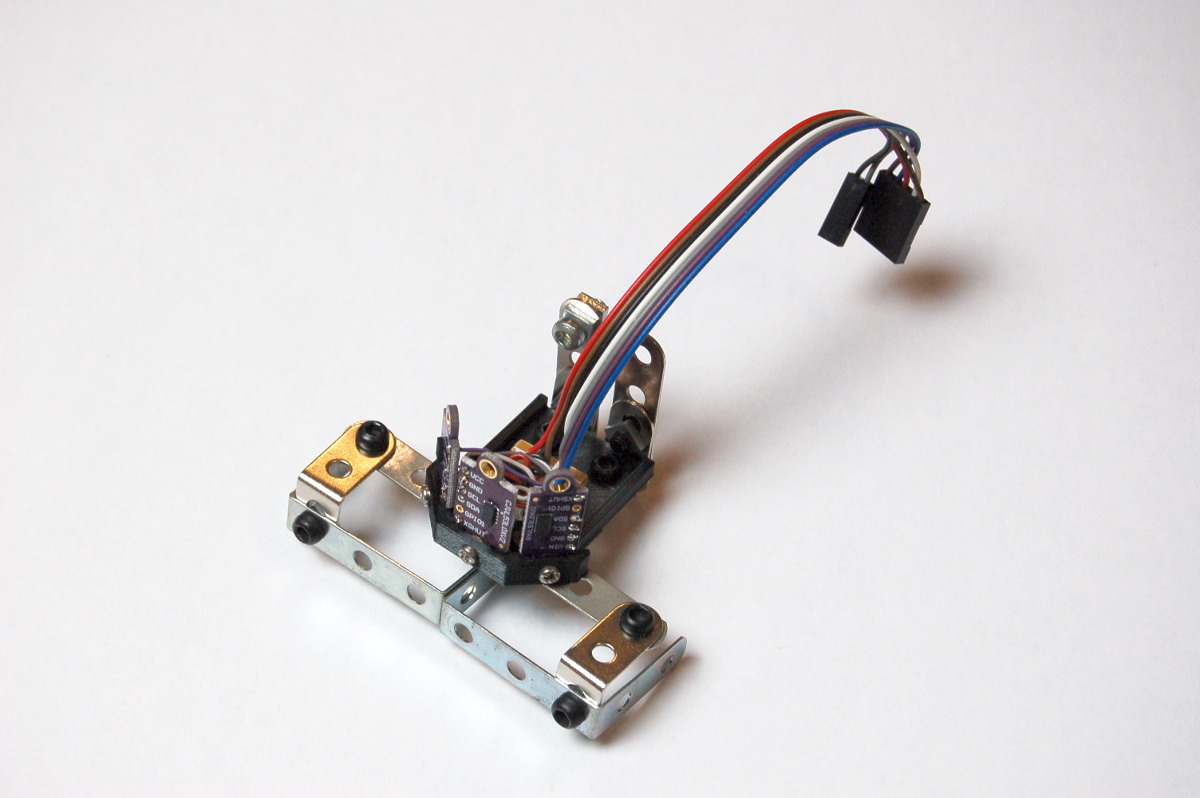
The FAROS is an extra attachment that can be connected to the front of the PM-1. It has three VL53L0X Time-of-Flight laser-ranging sensors and provides distance measurements at the front and 45 degrees left-right. It connects to the SIPS using I2C.
SOGU – Spherical Object Grabber Unit
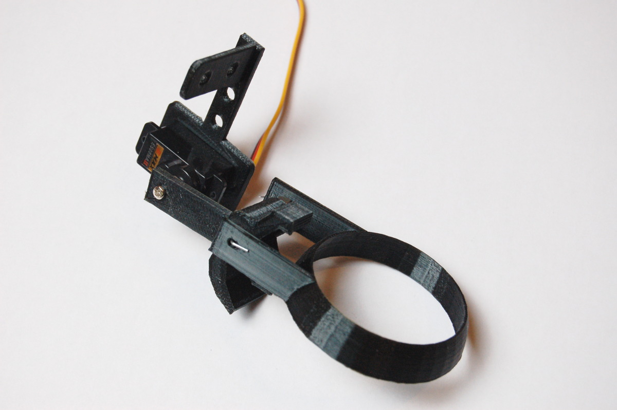
The SOGU is another extra attachment that connects to the front of the rover. As its name suggests, it’s specially designed to grab spherical objects, for example golf balls. The ring can be lifted up and down using a servo, and it’s intentionally loosely attached so that it can move around a bit when moving on uneven terrain or slopes.
And finally, here is the fully assembled “final” version of the rover!
Comparing it with the carcass of the MRV0.3 prototype: